CURRENT SENSOR
Product series:
Product part number:
Version:
STK-CTS/xx
STK-20CTS/DT
STK-30CTS/DT
STK-20CTS/T
Ver 3.6
CONTENTS
1. Description
2. STK-20CTS/T & STK-20CTS/DT parameters
3. STK-30CTS/DT parameters
4. Frequency band width
5. Step response time
6. Frequency delay performace
7. STK-CTS/DZ: Dimensions & Pins & Footprint
8. STK-CTS/Z: Dimensions & Pins & Footprint
9. TYPICAL APPLICATION CIRCUIT (STRING)
10. TYPICAL APPLICATION CIRCUIT (ARC CURRENT)
1. Description
STK-CTS/xx series current sensors are based on open loop principle with TMR technology. The sensor can detect those current with DC, AC, pulse and irregular wave shape. Because of its very wide frequency band width of DC ~ 700 kHz, the sensor can detect both of string current and the ARC current at the same time. With build-in coil, the sensor supports the self-check function.
Typical application
String current in PV
MPPT
AC current detection
ARC current detection
Variable speed driving
Switch mode power supply
General parameters
Parameter
Symbol
Unit
Value
Working temperature
T_A
℃
-40 ~ 85
Storage temperature
T_stg
℃
-40 ~ 105
Mass
m
g
10
Absolute parameters
Parameters
Symbol
Unit
Value
Supply voltage
VC
V
6
ESD rating (HBM)
UESD
4
![]() V
V
Remark: the unrecoverable damage may occur when the product works on the conditions over the absolute maximum ratings. Long-time working on the absolute maximum ratings may cause the degradation on performance and reliability .
Isolation parameters
Parameter
Symbol
Unit
Value
Remark
Isolation voltage, 50 Hz, 1 min
Ud
4
Clearance
mm
> 8
Shortest distance through air
Creepage distance
dCp
mm
> 8
Shortest distance along device body
Case material
V0 according
to UL 94
![]() V
V
![]() CI
CI
2. STK-20CTS/T & STK-20CTS/DT parameters
Condition: Vcc = 5.0 V, T_A = 25℃ , unless specified.
Parameters
Symbol
Unit
Min.
Typ.
Max.
Remark
Primary current
I_pn
A
20
Maximum
current
I_pm
A
-20
20
Supply voltage
Vcc
V
4.75
5
5.25
Consumption
current
Icc
4
Self-checking
current
2
2
The current requested for self-checking function
Build-in coil resistance
Rlm
ohm
2.8
100-turns build-in coil
Build-in coil impedance
XLck
ohm
80
@ 10 kHz
Full-scale
output
V FS
_
V
2
((Vout@I_pn)-(Vout@(-I_pn)))/2
Output
resistance
Ω
10
@ Vout
Offset voltage
Voff
V
2.48
2.5
2.52
Vout @ 0 A
Theoretical gain
mV/A
100
2 V @ I_pn
Gain error
%G_th
-0.5
0.5
Adjusted @25℃
Non-linearity
Non-L
%I_pn
-0.5
0.5
± I_pn
Step response time
t_res
μs
1
@90% of IPN
Delay time
t_delay
μs
1
@ 500 kHz
-3 dB band
width
BW
kHz
500
Noise
DC ~ 10 kHz DC ~ 100 kHz
Vnoise
mVpp
15
25
Accuracy @ RT
X
% of
I_pn
- 1
1
@ 25℃
Accuracy
X_TRange
% of
I_pn
-2.5
2.5
-40℃ ~ 85℃
![]() A
A
![]() I ck
I ck
![]() A
A
![]() R out
R out
![]() G th
G th
![]() Err G
Err G
3. STK-30CTS/DT parameters
Condition: Vcc = 5.0 V, T_A = 25℃ , unless specified.
Parameters
Symbol
Unit
Min.
Typ.
Max.
Remark
Primary current
I_pn
A
30
Maximum
current
I_pm
A
-30
30
Supply voltage
Vcc
V
4.75
5
5.25
Consumption
current
Icc
4
Self-checking
current
2
The current requested for self-checking function
Build-in coil resistance
Rlm
ohm
2.8
100-turns build-in coil
Build-in coil impedance
XLck
ohm
80
@ 10 kHz
Full-scale
output
V FS
_
V
2
((Vout@I_pn)-(Vout@(-I_pn)))/2
Output
resistance
Ω
10
@ Vout
Offset voltage
Voff
V
2.48
2.5
2.52
Vout @ 0 A
Theoretical gain
mV/A
66.7
2 V @ I_pn
Gain error
%G_th
-0.5
0.5
Adjusted @25℃
Non-linearity
Non-L
%I_pn
-0.5
0.5
± I_pn
Step response time
t_res
μs
1
@90% of IPN
Delay time
t_delay
μs
1
@ 500 kHz
-3 dB band
width
BW
kHz
500
Noise
DC ~ 10 kHz DC ~ 100 kHz
Vnoise
mVpp
15
25
Accuracy @ RT
X
% of
I_pn
- 1
1
@ 25℃
Accuracy
X_TRange
% of
I_pn
-2.5
2.5
-40℃ ~ 85℃
![]() A
A
![]() I ck
I ck
![]() A
A
![]() R out
R out
![]() G th
G th
![]() Err G
Err G
4. Frequency band width
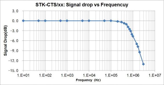
Fig. 1 the band width of STK-CTS/xx series current sensors.
5. Step response time
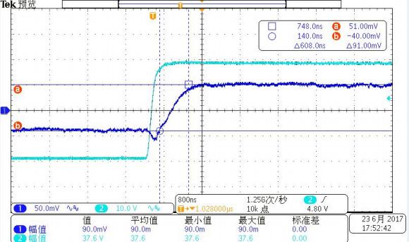
Fig.2 the step response time of STK-CTS/xx current sensors. The light blue is primary current, while the dark blue is output signal of current sensor. The step response time is less than 1 μs.
6. Frequency delay performace
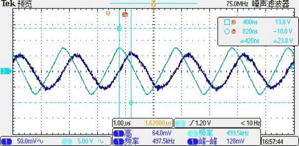
Fig.3 when detection the primary current with a frequency of 500 kHz. The delay time from primary current (light blue) to the output of the sensor (dark blue) is less than 1 μs.
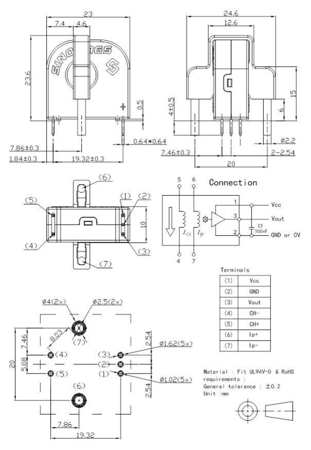
7. STK-CTS/DZ: Dimensions & Pins & Footprint
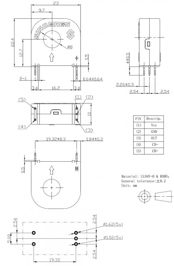
8. STK-CTS/Z: Dimensions & Pins & Footprint
9. TYPICAL APPLICATION CIRCUIT (STRING)
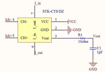
R1 (ohm)
C1 (nF)
Theoretical
-3 dB, f = 1/(2π RC), (kHz)
Measured
-3 dB, (kHz)
100
1
1592
~ 500
240
4.7
141
~ 150
2000
9.4
8
~ 10
10. TYPICAL APPLICATION CIRCUIT (ARC CURRENT)
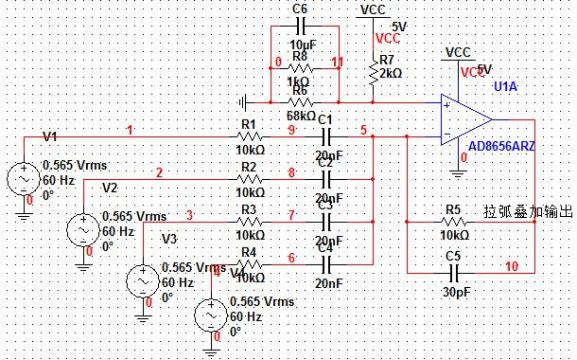
Note:
1 、 The band-pass setting: 1 kHz ~ 500 kHz.
2 、 The current for self-checking: frequency of ~ 10 kHz with amplitude of higher than 2 mA.
微信二维码
Copyright © 2022 无锡品联微电子科技有限公司 版权所有 本公司深耕8位、32位Cortex-M0+&Cortex-M4单片机应用开发和软件设计服务! 备案号:苏ICP备17072675号-1
技术支持: